
Once your crated ShapeArray™ has been lowered with the winch and you are reaching the top of the ShapeArray™ that is secured with zip ties to the reel, it is time to install the Weight Assembly installation hardware.
NOTE: This is one step in installing a Crated ShapeArray with a Weight Assembly. For a listing of the overall process, and the tools and equipment that will be required, please refer to Installing SAAV with a Crate and Winch System and Weight Assembly. Please ensure the steps are followed in order and that any steps prior to this one are completed before starting this step.
Step 1 – Lower the ShapeArray™ Into Position For Attaching the Weight Assembly
Continue lowering the ShapeArray™ with the winch. As you near the top of the ShapeArray™, zip ties will need to be cut to free the ShapeArray™ from the reel. Operators must stabilize the array while this is being done. Once freed from the reel, continue to the lower the ShapeArray™ until the Weight Assembly Collar near the cable terminator is sitting just above the borehole by 152.4 mm (6 inches) as shown in the figure below.
At this point, place the reel brakes under the reel to hold the reel in place with added safety.
NOTE: Ensure all materials listed in Installing SAAV with a Crate and Winch System and Weight Assembly are ready and close-by before continuing these instructions.
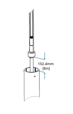
Figure 1 - Ensure there is 152.4 mm (6 inches) of room between the Weight Assembly collar and the casing.
Step 2 – Secure the ShapeArray™ with the SAAV Cleat
Remove the pin from the SAAV Cleat and place it below the Weight Assembly collar and around the terminator segment at the top of the borehole’s casing. Insert the SAAV Cleat’s safety pin and secure the wire lock in place. Slowly lower the array with the winch system so that the Weight Assembly Collar rests on the SAAV Cleat’s top plate, taking care that it firmly contacts the insert on top of the SAAV Cleat. At this point, the ShapeArray™ should be suspended in the casing and fully supported by the SAAV Cleat.
WARNING: Ensure that the safety pin is secured in place on the SAAV Cleat. The instrument is not securely supported until this pin is properly locked into place.
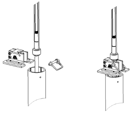
Figure 2 - Use the SAAV Cleat to safely hold the array in place.
Step 3 – Install the Weight Assembly
Locate the Weight Assembly in preparation for the next few steps.
NOTE: After locating the Weight Assembly, DO NOT REMOVE the small piece of Teflon tube located on the bottom of the assembly. This will protect the cable while you are threading it through the center of the weight assembly prior to connecting it to the ShapeArray’s cable terminator.
WARNING: Watch out for pinch points between the slugs on the Weight Assembly and ensure operators keep their hands clear.
With the ShapeArray™ supported at the top of the borehole casing by the SAAV Cleat, remove the communications cable from inside the crate or reel by cutting the zip ties that are holding it in place.
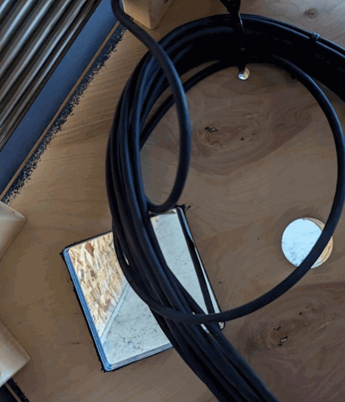
Figure 3 – Remove the zip ties holding the cable inside the reel.
Take careful note of the placement of each colored wire in the connector at the end of the cable as re-wiring this connector later will be important to the smooth operation of the ShapeArray™.
NOTE: It is good practice to take a reference photo of the connector wiring prior to disassembling the connector.
Remove the connector from the cable so that the cable can be fed through the Weight Assembly.
Use one wrap of thin tape to bundle the wires at the end of the cable together. Feed the cable into the white plastic protector on the 3/8” coupler and through the Weight Assembly. One person must hold the Weight Assembly while the other gently pulls the cable through.
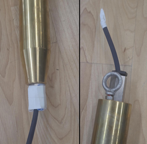
Figure 4 – Wrap cable wires with thin tape and feed the cable through plastic protector on the coupler of the weight assembly.
When the communication cable is successfully threaded through, the Teflon tube may be removed and some medium strength thread locking compound should be applied before threading the Weight Assembly to the terminator of the ShapeArray™. Hand tighten the Weight Assembly to the cable terminator as much as possible.
Attach two vise grips or pipe wrenches, one on each of the adapters (see figure below), to tighten the weight assembly firmly and wrench tight. Take care to ensure that the x-mark label is not disturbed, and that the steel cables are not pinched or damaged.
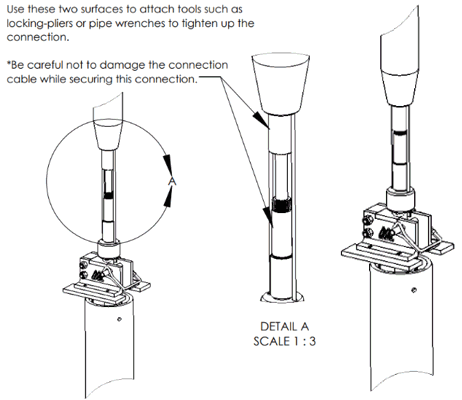
Figure 5 - Steps for Installing Weight Assembly presented from left to right.
The pliers may now be removed, and the reel can be rolled forward to release tension in the steel cable.
WARNING: The Weight Assembly is heavy and precariously balanced on the SAAV Cleat at the top of the borehole casing at this point. An operator should always have their hands on the Weight Assembly to steady it while the subsequent operations are occurring.
Step 4 – Prepare to Respool the Winch
The winch can install a maximum length of 110 m from the point where it was first connected to the reel. If the installation length of the array attached to the winch is longer, or the depth into the borehole exceeds 110 m beyond this point, you will need respool its cable. To facilitate respooling the winch, the support cables attached to the Weight Assembly must be changed around to temporarily free it from the reel and allow the reel to turn freely from the ShapeArray™.
To begin, roll the reel forward (turn the winch counterclockwise) to locate the 1/8” steel cable on the reel that is attached with a quick link to the cable collar cables on the ShapeArray™. Keep rolling the reel forward to relieve tension until you can easily open the quick link, remove the two loops from the ShapeArray’s cable collar cables, and attach the quick link to the eyelet of the Weight Assembly.
Roll the reel backward (turn the winch clockwise) to take up any slack in the Weight Assembly connection.
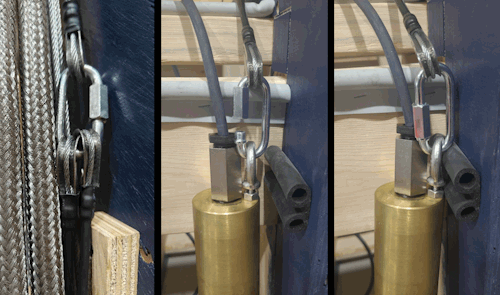
Figure 6 - To support the Weight Assembly, remove the cable collar cables from the quick link and attach to the eyelet (left to right)
The ShapeArray™ and Weight Assembly should now be supported by the cable connected to the reel, the SAAV Cleat hardware at the top of the borehole casing, and an operator to keep it from tipping.
The ShapeArray’s cable collar cables should now be looped around the base of the crate. Insert them through the forklift pocket in the base and thread them to the front. Place each end loop on either side of the cable and, using a quick link, attach the cables together to close the loop. This will provide safe anchoring for the ShapeArray™.
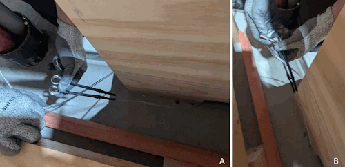
Figure 7 - Loop the cable collar cables around the front forklift pocket (A) and attach them together on either side of the cable with a quick link (B)
With the anchor in place around the base of the crate, the quick link attached to the weight assembly’s eyelet may now be removed. The loose cable on the reel should now be secured to a rung on the reel with a zip tie to ensure it does not unravel while you respool the winch.
The reel is now free to move, and the winch can be respooled by turning the nut on the winch clockwise. Once the winch is respooled you can remove the zip tie securing the cable loop on the reel and reattach it to the eyelet of the Weight Assembly. Once the reel cable is re-attached to Weight Assembly’s eyelet, roll the reel backwards (turn the winch clockwise) to apply tension to the cable and provide support to the ShapeArray™.
Before continuing with the installation, cut the ShapeArray’s cable collar cables and remove them from the array. Steel cable shears should be used to cut the cable.
WARNING: When cutting steel cable there should be no tension in the cable. Ensure the cable is slack prior to cutting with cable shears while wearing appropriate eye and abrasion protection. The ends of the cut cable will be sharp.
Step 5 – Finish Lowering the ShapeArray™
The reel should be rolled backwards (turn the winch clockwise) to slightly lift the ShapeArray™ and Weight Assembly off the SAAV Cleat. The SAAV Cleat can now be removed by opening the safety wire and removing the pin. Reassemble the SAAV Cleat after removing it and set it aside in the accessories crate.
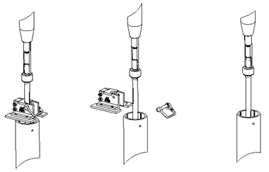
Figure 8 - Remove the SAAV Cleat (left to right)
The array may now be lowered into the borehole by rolling the reel forward (by turning the winch counterclockwise) until the instrument has settled on the bottom of the borehole. The communication cable should be taped to the steel cable at regular intervals to ensure it does not bunch up or become entangled as the ShapeArray™ is lowered into the borehole.
WARNING: While the instrument is being lowered into the borehole, make sure that there is an operator ready to engage the brakes when needed.
Once the array has reached the bottom of the borehole, carefully replace the connector onto the end of the communication cable. Refer to the reference picture of the connector taken prior to removal to ensure correct wiring.