
Once you have setup and unboxed your ShapeArray Crate, it is time to assemble the Crate's winch system and begin the installation.
NOTE: This is one step in installing a Crated ShapeArray with a Weight Assembly. For a listing of the overall process, and the tools and equipment that will be required, please refer to Installing SAAV with a Crate and Winch System and Weight Assembly. Please ensure the steps are followed in order and that any steps prior to this one are completed before starting this step.
Step 1 - Prepare for Installation
Because of the weight of the instrument and reel, it is recommended that at least five operators be available to continue the installation. Have these operators move into the following positions:
- Three operators are needed to manage the weight and rotation of the reel during the installation process. They should be positioned on each end of the reel and in the middle to control the rotation of the reel.
- One operator is needed to guide the ShapeArray’s segments coming off the reel into the borehole. This operator should be facing the instrument on the reel.
- Another operator is required to engage and disengage the brakes for the reel. When this operator is in position, they must slowly remove the brakes while the three operators controlling the reel begin to take the weight of the array.
NOTE: Communication is very important. If any of the operators are not in a comfortable position, call out for the brakes to be engaged. This will allow a chance to reposition or swap operators. Only one brake is necessary to hold the reel for a short time, but the second brake should be engaged if a break over 1 minute in length is needed.
With all operators in position, hold the bottom segment of the ShapeArray™ (with the eyebolt) to prevent it from springing away from the reel due to tension. Clip the zip tie that holds the bottom end of the instrument to the reel.
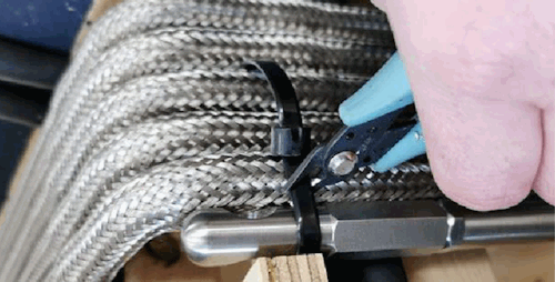
Figure 1 - Clip the zip tie to detach bottom end of ShapeArray™ for installation.
Step 2 – Begin Installing the ShapeArray™ into the Borehole
Slowly install the ShapeArray™ down into the borehole by unreeling the segments and guiding them into the conduit. Ensure the segments entering the conduit remain vertical and avoid having them make contact with the top of the casing to prevent any chance of bending a segment. Continue to unreel the ShapeArray™ into the conduit until the top section of the instrument is the only portion that is attached to the reel. The stopping point is clearly marked by labeling on the ShapeArray’s segments.
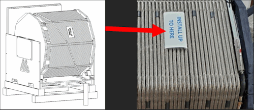
Figure 2 – Install ShapeArray™ until you reach the label.
When you reach the label, apply the reel brakes.
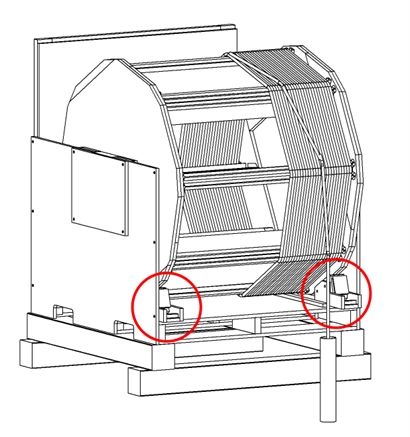
Figure 3 – Pause and apply the reel brakes when you reach the label.
Step 3 – Install the Winch System
Finish removing the packing materials from the small accessories crate to reveal the Winch System at the bottom.
WARNING: The winch system uses braided steel cable. Eye protection (safety glasses), as well as hand protection (cut resistant gloves) are required to remain safe during the installation. If any sections of aircraft cable become frayed, discontinue use immediately until the affected cables can be replaced.
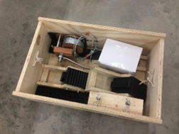
Figure 4 – Unboxing the Winch System from the small accessories crate.
Remove the Winch System assembly from the small crate.
NOTE: Do not cut off the packaging from the winch system (zip ties/tape), as it will be helpful to complete the following steps.
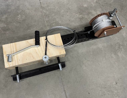
Figure 5 – The Winch System unboxed.
Remove the retaining nuts and bar from the winch system with a 5/8” socket.
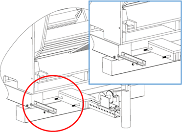
Figure 6 - Remove the retaining nuts and bar from the winch system.
Insert the Winch System into the bottom of the large ShapeArray™ crate on the left-hand side (facing the reel).
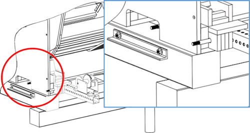
Figure 7 - Insert the Winch System into the ShapeArray™ crate.
Secure the Winch System to the crate by replacing the bar onto the threaded rods, and then securing the bar to the threaded rods with washer on long metal nut in each place.
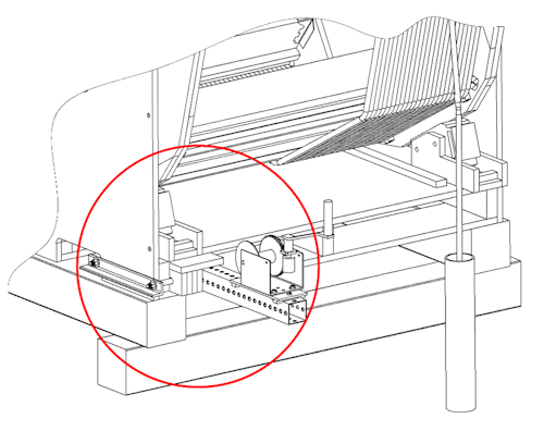
Figure 8 - Secure the Winch System to the ShapeArray™ crate.
Remove the zip ties and packaging from the winch system, and then connect the cable to the reel with supplied hardware in the ‘pre-drilled’ holes.
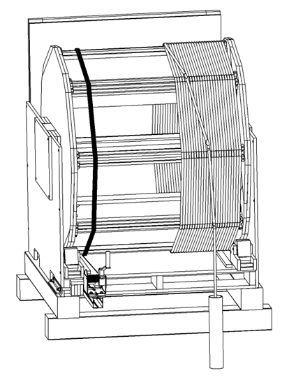
Figure 9 – Winch System secured to crate and cable secure to rung.
Wrap the cable loop around a rung that is approximately 300 mm (12 inches) from bottom of crate and facing bore hole. This should be done to allow enough room to wrap the looped cable end completely around the rung, and then secure it with the provided washers and fasteners.
Use a 7/16” socket or wrench to firmly tighten the anchor onto the rung.
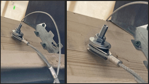
Figure 10 – Attach the Winch System to the crate rung by wrapping around the rung and securing with washers and fasteners.
Apply tension on the cable manually with the supplied handle by rotating the winch in the clockwise direction, and then you can safely release the supplied reel brakes from holding the array.
WARNING: Keep the brakes in position for quick engagement in case of emergency and have an operator ready to apply them.
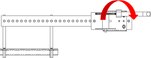
Figure 11 – Turn the winch handle clockwise to apply tension to the cabling between the reel and the winch.
At this point, the Winch System is bearing the load of the ShapeArray™. A powered hand drill with a 5/8” socket operating at 500 RPM up to 2000 RPM can also be used to operate the winch at a quicker pace. Turn the hex drive on the winch in a counterclockwise direction at a consistent and manageable rate. The ShapeArray™ will continue to unreel into the borehole while the winch’s cable will begin to spool around the rungs of the crate.
NOTE: It is recommended to have multiple batteries for the hand drill close by during installation. It is also recommended to take breaks or use multiple drills during installation to prevent overheating of the hand tool.
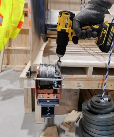
Figure 12 - Installing using hand drill at 500 – 2000 RPM
Continue lowering the ShapeArray™ with the winch until you near the top of the ShapeArray™ that is secured with zip ties to the reel.